Semisubmersibles and fatigue life extension

There are many semisubmersible rigs which have reached or soon will reach their design service life. Furthermore, some shipyards have built several similar rigs according to more or less same drawings several fatigue hot spots found in one of these rigs will correspond to similar locations on sisters rigs. However, an updated FEA showing hotspots stress locations are needed to exact locate and assess the extension of these fatigue sensitive locations. These location will then require the application of fatigue life improvement techniques and in doing so the life extension of the entire structure could be achieved.
Classification societies normally recommend to the operator a fatigue life improvement technique which is acceptable for the required work and which will enhance the fatigue resistance and ensure structural integrity. The most fatigue sensitive locations are main columns, their connections to pontoons, braces connections to main columns, inside welds in braces, flare tower, among others. These works are normally carried out during maintenance stops of the installation.

Relevant stress ranges considered for fatigue life extension

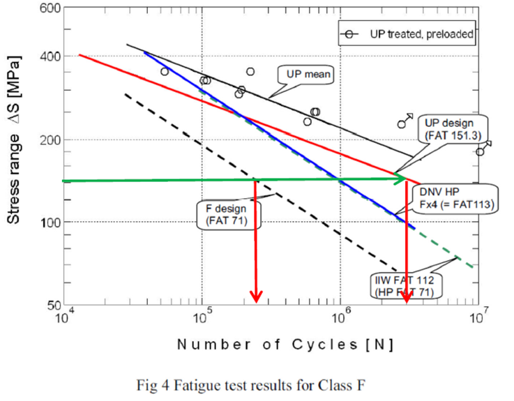
The relevant stress ranges have been chosen from the exceedance probability and the accumulated exceedances diagrams. These take into account the long term stress range distribution and with a Weibull shape parameter h≈1.0 where the major contribution to fatigue damage occurs around 10 mill cycles. Approximately half the damage occurs at number of cycles below 10 mill cycles and the other half above 10 mill cycles. Therefore it is not relevant to design this specific welded detail for 264 MPa which is the maximum stress range indicated by the calculations since the exceedances of probability and accumulated exceedances for that specific stress range are too low. As a result we will compare the fatigue lives for the selected stress ranges: 160 MPa, 125 MPa and 88 MPa to the fatigue lives of the same welded detail treated by ultrasonic peening. The most important part of the long-term stress range distributions is for actions having a probability of exceedance in the range 0.0001 to 0.01 which is represented here by 125 MPa and 88 MPa.

Assessment of Life Extension

All the comparisons are normally done for SN-curves (as-welded and ultrasonic peening treated) showing in every case the mean values minus two standard deviations. Stress Range 160 MPa: (see green and orange lines in Diagram) Number of cycles for the as-welded condition is 250.000 cycles. For the as-welded plus ultrasonic peening treated condition the number of cycles is 3.000.000 cycles. This gives a fatigue improvement in life of 12 times. Due to uncertainties as fatigue test specimen size, estimation of external loads among others it is reasonable and conservative to decrease this value 20 % being then the potential fatigue life extension 9.6 times. This will give a fatigue life after the ultrasonic peening treatment of 4.52 years x 9.6 times = 43.4 years as a conservative estimate at the base of column. The two other stress ranges mentioned above will give even longer fatigue lives and therefore these do not need to be further considered.