Fatigue Life of Welds

Fatigue Life of Welds

Fatigue strength of welded joints

The allowable design stress of structures subjected to fluctuating service load is nearly always governed by the fatigue strength of welded joints, particularly any fillet weld present. The poor fatigue strength of such joints, which in the as welded condition is also independent of parent steel strength , can be attributed to the conjoint effect of three factors:

  • a. local stress concentration due to geometric discontinuity
  • b. the presence of sharp crack like flaws such as undercuts and slag intrusions introduced by the welding process
  • c. the presence of large tensile residual stresses in the weld metal and the surrounding heat affected zone (HAZ)

Global stress concentration

Every welded joint gives rise to a geometric discontinuity associated with the change in section at the connection. When loaded the discontinuity will result in stress concentration which increases the magnitude of local stress. The extent of stress concentration will depend on how abrupt the change in section is: fillet welds with convex profile and small toe radii produce the largest stress concentration and butt welds with relatively flat overfills produce the smallest. However, the stress concentration resulting from the weld detail itself can be significant.
Incidentally, the effect on global stress concentration of the detail itself, can explain why other factors being the same, fillet welds behave generally worse than butt welds. Also it explain why some nominally non-load carrying details have such poor fatigue strength. A notable example is the longitudinal stiffener with fillet welds all around which depending on the stiffeners length and its proximity to free edges can have a fatigue design classification C. The reason for the low fatigue class is simply the attraction and the pertinent concentration that the stiffener exerts on the load paths at its two ends, leading to highly localised and sharp stress gradients at those specific locations.

Weld flaws

Undercutting of the plate surface often occurs at the toe of most welds, leading to a source of local stress concentration. Also, in most welds produced ndudtrially and regarded as having acceptable quality , the presence of sharp , almost crack-like , slag intrusions, inclusions, etc. cannot be ruled out. These weld flaws are normally too small to be detected by routine non destructive examination. Nevertheless, by acting as ready sites for fatigue crack initiation they have a profound effect on the endurance behaviour of welded joints. By removing any significant fatigue crack initiation, they ensure the fatigue life of a welded joint is spent almost entirely in crack propagation. And as crack propagation properties of most steels are essentialy similar, the presence of weld flaws results in fatigue behaviour of the detail being essentially independent of parent steel grade.

Residual stresses

During welding, high tensile residual stresses form in the weld metal and surrounding HAZ. These residual stresses arise primarily from differential contractions during cooling, but thermal gradients during cooling and a volume change associated with phase transformation in some materials can also contribute to the total residual stress distribution. These residual stresses combine with the applied stresses to increase the effective mean stress. Thus applied compressive stresses can be as damaging as applied tensile stresses and fatigue failure can occur even under fully compressive loading. Incidentally, another important effect of welding residual stresses is that in fatigue design of welded joints only the stress range, that is the difference between the minimum and the maximum applied cyclic stress, needs to be taken into account. The applied mean stress, an important parameter in fatigue design of unwelded components and improved welds, plays no role in the design of welded components in the as-welded condition. This is because with large tensile residual stresses present, the weld experiences high mean stress even when the applied stress is low.

Fatigue life improvement techniques

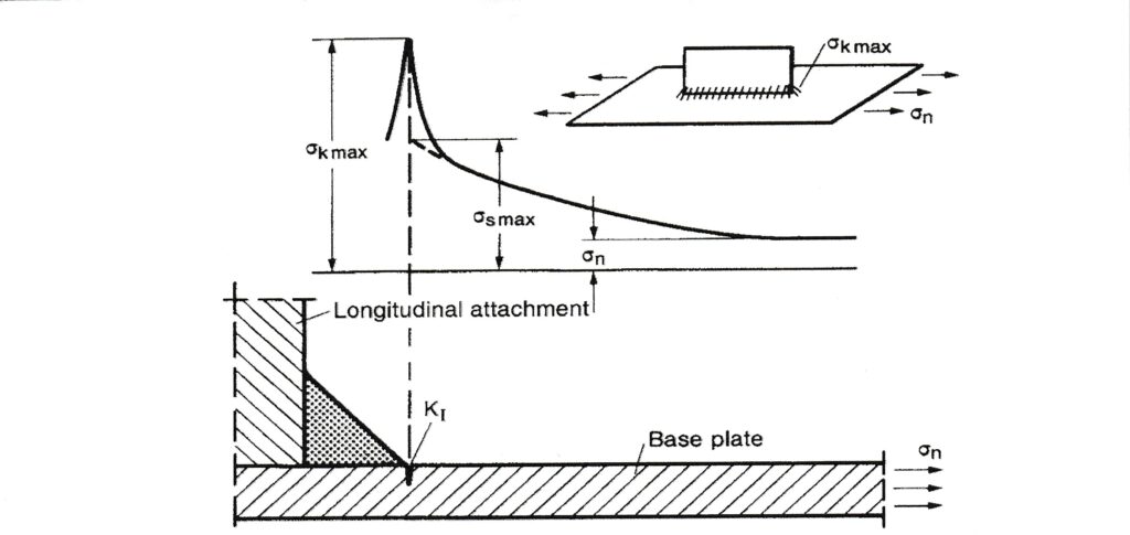
The fatigue life improvement methods are grouped into two classes: weld geometry methods and residual stress methods. The former methods are designed to reduce the stress concentrations due to the weld geometry and remove or reduce crack-like flaws (defects) at the weld toe. The latter methods introduce compressive residual stresses in the regions where the fatigue cracking is likely to occur. Grinding (either whole profile grinding or weld toe grinding), peening (needle peening or hammer peening), tungsten inert gas (TIG) dressing, and ultrasonic impact technique (UP), are currently used to improve the fatigue life of welded joints.

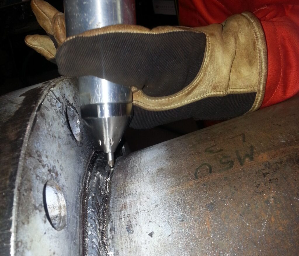
However, ultrasonic peening is the only technique which effectively reduce the local stress concentration and simultaneously replace tensile residual stresses by beneficial compressive residual stresses.

Ultrasonic Peening

The ultrasonic peening treatment consist of introducing a groove at the weld toe, removing possible crack prone areas and generating compressive stresses during the same and solely operation. The effect of removing weld imperfections at weld toe and the introduction of a weld groove, which decreases permanently the geometrical stress concentration, have undisputed benefits which are also easy to quantify.